myR: sensore ultrasuoni

The ultrasound sensor is used to measure the distance respect an item in front of it.

A basic ultrasonic sensor consists of one or more ultrasonic transmitters (basically speakers), a receiver, and a control circuit. The transmitters emit a high frequency ultrasonic sound, which bounce off any nearby solid objects. Some of that ultrasonic noise is reflected and detected by the receiver on the sensor.

WP_20160212_002

There are a bounce of tutorial on how to use it.I  just follow this perfect tutorial :

www.modmypi.com

In this post I want to focus the sw code I developed and I just post the wiring:HC_SR04_2

The module is called us_sensor.py and it is upload in  Github>>myRover.

Inside you can find an class object called us_sensor_data, that collect the information to share with the world (the distance in [mm] and the period of  measurements in [sec].

This choice to create a separate class will become very useful when I will put all togheter (in the rover.py). In this way any  object can see all the information from other objects.

The main class  is the us_sensor  object.

def __init__(self, name, trigpin, echopin, data):

Where you need to pass a name, the GPIO pin for the trig signal (output) and the GPIO pin for the echo (input) signal.

This object  works in a parallel thread (threading.thread), so while in your main loop you can do something, the us_sensor continuously (every data.period time) measures the range and put this information in data.distance.

Since it is parallel thread you need to start it first,by calling  mySensor.start(). This call recalls then the run(), where there is the measurement loop.

Then you need to stop it when closing the application , and mySensor.stop().

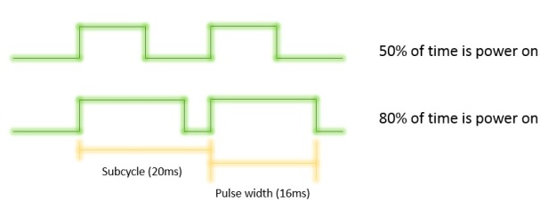
Note that if you have more threads running  the measurements become less precise.

In addition if an item is very close to the sensor it happens to loose some echo signal.In order to avoid the loop to freeze waiting for a signal that was lost, I manege also a timeout.

Finally you can find a main()  to test the sensor by itsself.

#init data class
data = us_sensor_data()
#init sensor
mySensor = us_sensor('HC_SR04', 4, 17, data)
mySensor.start()
#from this moment the sensor is measuring and puts the result in mySensor.data.distance
...
while mySensor.cycling:
     #here do something...
     ...
     #than get the info when you need it
     s = 'Distance: ' + str(mySensor.data.distance)
     ...
finally:
# shut down cleanly
...
mySensor.stop()

myR:Come controllare DC motor.3

This 3rd part is dedicated to the sw .

I use an approach object-oriented, so I prefer to create for each real component a equivalent sw  class object. It means that I try to include in the code all the parameters necessary to describe the item and its behavior.

The advantage of this approach is that if I need 20 motors, I just initialize 20 istances of my DCMotor Class.

The translation of this concept is very simple:Which parameters can describe can describe my motor?

The fundamental information is:  which is its speed? and than which are the limits of this speed?

Again, How phisically can control the motor, so which pins are used to set the speed?

All of this information are included in the init() of my class:

def __init__(self, name, MBack, MForw, channel1, channel2, WMin=-100, WMax=100, Wstall=30, debug=True,simulation=False):

MBack is the GPIO pin used to move the motor Backward, channel1 is the DMA channel used for it.

MForw is the pin for motor Forward. channel2 is the DMA channel used for it.

Wmin and Wmax is intuitive…

WStall is the  minimun speed that cause the motor not to move.

The actions that can be done onmy motor are:

1)Start the motor – in reality this just initialize the GPIO channels and pins.

def start(self):

2)Stop the motor – stop the GPIO channel.

def stop(self):

3)Set the speed W – check the speed is inside the limits,check if the motor is requested to move backward or forward , reset the unsued pin and set the pulse width of the correct pin.

 def setW(self, W)

Finally  by calling in a main routine those functions you can move your motor:

myDCmotor = DCmotor('myMotor', 18, 23, 11, 12)
myDCmotor.start()
myDCmotor.set(30)
#accelerate
myDCmotor.set(80)
#deelerate
myDCmotor.set(50)
#move backward
myDCmotor.set(-40)
#brake
myDCmotor.set(0)
#stop
#myDCmotor.stop()

You can download the code from Github-solenerotech/myRover

NOTES:During the programming , also when I added other devices like picmaera and ultrasound sensor I notice some bad behaviour on the GPIO system.For this reason you can find in the code some choices that are explained by this problems.

1)I notice that it is necessary to use one channel for each pin. Otherwise the pulse width is inverded ( if I set W=90% it runs 10% ans so on).  Thats expalin channel1 and channel2.

2)the DMA channels are used to create the PWM. But the DMA channels in rpi are used also for other activity. So you need to avoid some of them, in particular DMA channel 0  is used for the system and DMA channel 2 is used for the sdcard. So avoid those 2 channels.

3)In order to generate a PWM you can use hardware clock or sw clock. The hw clock is used also by Picamera, so this can generate an interference to the picam itself. To avoid this I’m using the sw clock on the PWM. This is obtained by using in the PWM setuput the option delay_hw=PWM.DELAY_VIA_PCM

myR:Come controllare DC motor.2

So, let’s first complete the wiring.

Each motor needs 2 signals, one for the clockwise movement, one for the counterclockwise movement.

I’m using the  GPIO 18 ,23,24,25  connected directly to the 4 inputs of the bridge.See the diagram below.

DCmotor4

Consider Motor 1. When GPIO 18 is high , the bridge set the Out1  also High and Out2 is the ground. And the motor turns cw. When GPIO23 is High the bridge inverts the outputs, so Out1  become the ground and Out2 is High and the motor turns ccw.

Finally , as we see in preview post, modulating the pulse width of the signal we can control the speed of teh motors.

myR: come controllare il DC motor

So let’s start  by moving the rover!

In my case I have 2  DC gear-motors with this specifications:

  • Gearbox: 4.8~7.2V
  • No load current:190mA(max.250mA)
  • Stall current: ~1A
  • No load speed: 90±10rpm
  • Torque: 800gf.cm

The control of this type of motor is really simple: when power on, it moves, when disconnected it stay still. Simple!

So what we can do is tuning the motor speed by  power on and off the motor itself using pulses of different width: we  will use the PWM (pulse width modulation).

DCmotor1

So consider  to send a pulse every 20ms (subcycle=20ms)  and  the pulse width is 16ms, than the motor stays on for the 80% of the time, while if the pulse width is 10ms it stays on for 50% of the time.

The motor can drain up to 250mA .It is too much for our raspberry output, so we need  a  bridge  in between than can guaranty this current.

That’ s why in the Bill Of Material I have the L298N bridge.

This board receive the input from rpi and send an output of the same width , with a signal level (voltage and current) depending on the power in  you connect ( the used battery pack).

In particular , the bridge I’m using can drive up to 2 motors.

DCmotor2

Below  the schema for the power connection. Note that the bridge can also provide a 5 V output than can be used to power the raspberry.

DCmotor3

In the next post, I’l explain how to connect the outputs and how to control them by software.

myR: sotto l’albero di Natale…

Under the xmas tree,  Santa put a  present for me including:

  • Dagu 4D MAgician Chassis (including 4 DC motors, and  2 plastic plates,4 x AA butteriy holder) -21 Eur
  • HC-SR04 sensor (a ultrasound sensor for measuring distance) -4 Eur
  • L298N bridge ( a bridge for controlling up to 2  motors) -4,5 Eur

In addition I had already:

  • raspberry pi
  • Pi cam
  • a wifi adapter
  • an omniwheel (spherical)
  • an empty  tic-tac candy holder
  • 4 X aa Batteries
  • a smartphone battery pack (2.5 A)

So I put every togheter and it pops out myR:  a super Rover!!!

WP_20151204_008

Nothing special under the sky, but an interesting project  to test autonomous veicles. So, to reach that goal , I’m now working on  a rover that can act in this 4 modes:

  • Jog mode, moved by operator ( my 5 years old son…).
  • Program mode: it is possible to create a sequence of movements and the rover can repeat them.
  • Discover mode: the rover can move randomly aroud the appartment avoid any obstacle in fornt of him.
  • Search mode: the rover can search and reach a ball placed or moved around.

As always I’m developing this features using python and  using object-oriented programming: for each item I create a module that implements all  the necessary features for this item.

In the next weeks I’ll post the development steps.

Happy new year and Keep in touch!

Are you still updating the blog?

In the last months I received  questions from followers  and from private e-mails about the state of  my project and this blog.

I reduced to zero the development mainly for the birth of my second baby. In addition my new job position did the rest : no more nights to dedicate to  my quadcopter.

I just  try a couple of time to fly : in  the second time in particular I obtained a broken prop…

By the way, It is really exciting to me, see so many contacts daily evenif I’m not for 6 months.

This give me new energy to restart.

So I cannot promise it , but I’ll try to be back on track!

Sulla calibrazione dell’IMU

I’d like to put here some consideration about the imu calibration, that means how it is mounted the imu on the drone respect the propeller plane. This information is fundamental to garanty a perfect hover position without lateral mevement of the drone.

In other words, if I set roll=0 and pitch=0 I want that the prop plane is aligned with the world, evenif the sensor can be not perfectly aligned with the world (and also with the propeller plane).

In this pictures you can see this case: the world (blue) , the sensor (red) and the prop plane ( orange).

IMU_cal1 IMU_cal2

In the next picture let’s put some manes to the angles:

IMU_cal3

Important: Note that gamma is the angle measured by the accelerometer.

The most important information I need to know is the angle beta : the offset between the sensor and the prop plane . this is the error generated to the mechanical installation of the imu.

This value is used to compensate the measured value from the accelerometer.

alpha and beta are the 2 unknowns so I need 2 equations to solve this problem.

I decide to use this simple method to calibrate imu:

1) Take a reference plane ( my kitchen table) . It does not metter if it is not perfect alingned to the world, it is just enough it is stable.

2)Place from behind the prop plane on the “table roof”.

IMU_cal3b

3) Measure the angles of the accelerometer (gamma1).

4)turn the drone 180 degree respect yaw and place it again on the table roof.

5)Measure the angles again ( gamma2) .

6)consider that, in those 2 measurements, the alpha angle is constant ( i do not move the table…) , while the angle beta is equal but inverted ( due to the rotation of the drone).So the result is:

IMU_cal4


In order to manage this method in a easy way I added in the code the option called “fine calibration” .

The last version is now on github.

Just run the myQrc.py , move to the new mode “IMU” and follow the instructions.


myQrc Rilasciata

I just upload the last and final version of the myQ release candidate on github

DSC_6918

All the software has been debugged and tested.

All the functionalities are now stable.

I tested in different options (debug mode, netscan activated, sensor log) and the result is that I can run the main loop every 10 ms and get sensor data every 6 ms.

It can happen to have a delay on the sensor data loop when a log is added ( 2/3 ms).


I removed the webserver from the list of test to do, so it is not supported in this version of the software. The main reason is an instability when runnin gon raspberry. I have to investigate a more robust way to manage the comunication via browser.


Next time I will write a post the drone will be just landed…(after its first flight!!!)

myQrc. Aggiornamento sviluppo

Just a quick note of the current development.

I tested sucessfully:

  • ESC mode
  • Motor mode
  • sensor.py – I modify the calibration procedure.Now after a calibratin, you can see the angles really equal to zero.
  • display.py – add yaw in the kayboard command

Performance test: I can run the mian task and update sensor every 5ms.

(need to take care on log: everytime I add a log line this time goes up to 16ms ,probably it is the time to open ,write and close the file. So when flying ,do not use debug level).

I’m now facing on some problem with netscan function. The main scope of it is to monitor that the PC used to send command , is always connected to rpi. It is working fine whentested on laptop. In rpi is not so stable. I’m investigating on that.

Also the webserver has got some problems when running on rpi: if i double click on the browser button, sometime it freeze the main task: not so good… (I’m thinking to remove this funciton from version 1)

myQrc. Release candidate su GitHub

TODO Tradurre…

Hello, I just upload the myQ release candidate on GitHub. (see permanent link on the right).

It is derived by my beta3.py but includes many additional features:

  • a new display that can show the current state of the quadcopter( orientation and motors)
  • The possibility to switch between modes (init ESC, test Motors, tune PID an so on) .Any mode has got its own tab with an explanation of what yuo can do.
  • a web server that can provide a web page to be used as remote control.From any device using browser just connect to 192.168.0.1/myQ.html and you get the command page. (honestly it could be a little too slow for a quadcopter, it should be better to use socket messaging )

webserver

  • a netscan functionality in oder to be sure that quadcopter did not loose connection with the remote control

So finally it is time to move back to the field, load all this new things on the rpi and deeply test it!!!